Advertisement
The bilge of his boat was constantly wet, until he installed a dripless shaft seal by himself. Here's how he did it.
Just about every boat fitted with a conventional inboard engine has what is known as a "stuffing box" or "shaft seal." This seemingly inconsequential piece of equipment allows the prop shaft both to exit the boat and rotate while at the same time keeping the water on the outside.
Tip
These are fairly simple pieces of equipment and work by compressing packing material, usually flax, against the shaft between a housing unit and two nuts (one is a locking nut) mounted on the end of a length of reinforced hose. In turn, the hose is clamped to the shaft tube. When correctly adjusted, the shaft is free to rotate within the stuffing box, and water mostly stays out. Too loose, and it will leak excessively; too tight, and shaft wear will occur.
In fact, a properly adjusted traditional stuffing box is supposed to leak a few drops each minute when the boat is underway. This slight drip ensures that the packing is lubricated with water; however, it shouldn't leak when the boat is stationary. BoatUS Marine Insurance claims files show that badly leaking stuffing boxes are responsible for one in 20 boats sinking at the dock. Thankfully, there are now more modern mechanical stuffing boxes that don't leak at all, thus keeping the inside of the boat dry, something that I'd long wished for on Seaglass, my Grand Banks 32.
Technical Support
Degree Of Difficulty: Moderate to difficult
Tools and Materials:- Wrenches
- Allen wrenches
- Screwdrivers
- Rubber mallet
- Gear puller
- Rags
- Penetrating lubricant, like PB Blaster
- 800-grit wet/dry sandpaper
- Locking sealant
- PSS shaft seal from PYI, but other brands are available
Time: This project takes about four hours.
Cost: The cost depends on the size of seal needed; Mark's costs were about $250.
Your boat needs to be out of the water to undertake this project. Once that's done, here's how to do the job:
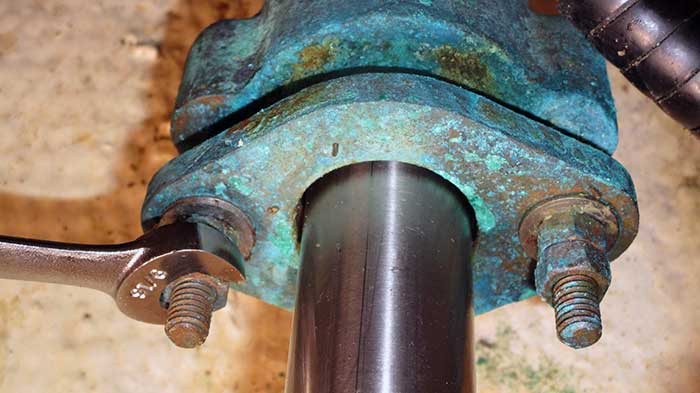
1. Loosen the packing-gland locking nut and the compression nut.
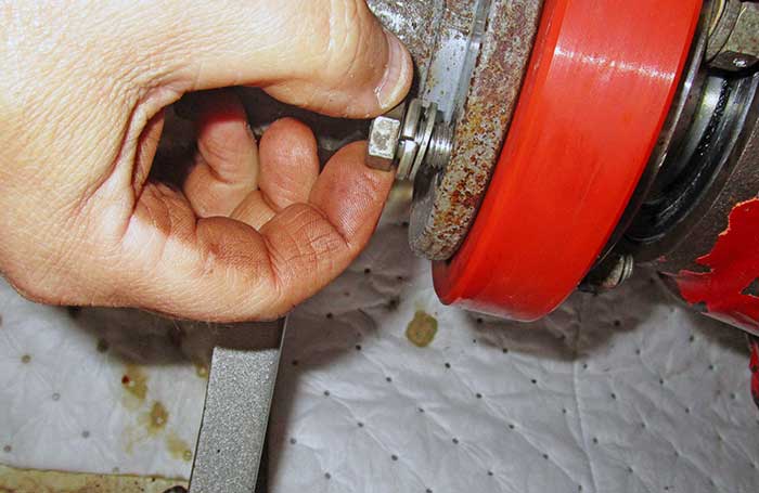
2. Remove the bolts that connect the transmission to the coupling. Depending on the boat, the size of shaft, and the power output, there may be four or six nuts and bolts. Slide the shaft toward the aft of the boat, about 10 to 12 inches.
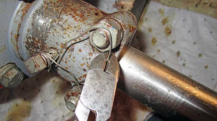
After cutting off any stainless-steel locking wire, remove the bolts or set screws that lock the coupling onto the shaft. My boat has a split coupling, but others are one piece. If your boat has a drive saver, as mine does, you'll also need to remove the grounding "jumper" cable or strap.
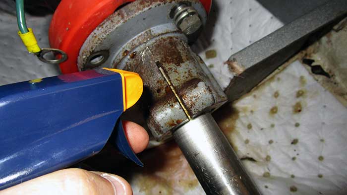
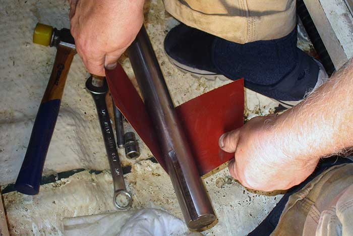
3. The coupling will be — or should be — tight on the shaft, as it has what is known as an "interference fit." In an effort to remove the coupling, don't hit it with a hammer because you could break the coupling or damage the shaft. Apply a good amount of a penetrating lubricant, such as PB Blaster, to the coupling, down the bolt holes, and to the face of the coupling where it interfaces with the shaft.
4. Allow the penetrating fluid to do its thing for 15 minutes or more. Then, gripping the shaft with one hand, carefully tap the back end of the coupling with a block of wood or a rubber mallet to get the coupling to slide forward off the shaft. Often, tapping on opposite sides of the back of the coupling helps. This may avoid cocking the coupling on the shaft, which, even if indiscernible, can make removal much harder. Never use a hammer, as you could break or distort the coupling, which is a fairly brittle casting.
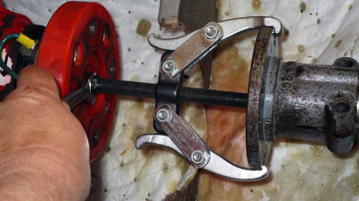
I cannot overemphasize the need for caution here. "Slow and steady" should be your mantra, not "fast and furious." Take your time; persistence will prevail. Sometimes you need a gear puller, but only if it's used carefully so as not to spread or distort the shaft or damage the coupling.
With the coupling removed, the hardest part of the job is now over. Undo the clamps that hold the old stuffing box and its hose to the shaft tube, and slide the entire assembly up and off the shaft. Sometimes it helps to support the shaft and propeller outside the boat.
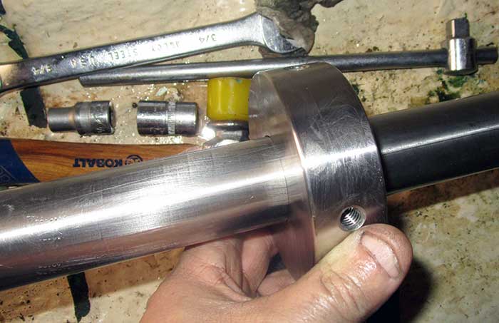
Inspect the shaft for pitting and wear, especially the end from which the coupling was removed. Also inspect the shaft where the original packing rubbed on the shaft. If these are at all wasted, bent, or damaged, you may need a replacement shaft. If in doubt, consult a prop shop or other professional.
5. Now is a good time to polish the shaft with some wet/dry sandpaper. Do not use anything coarser than 800-grit paper. The object of the exercise is to make the shaft shiny and smooth, not to remove lots of metal or put scratches in the shaft. Finally, wipe down the shaft with a clean rag to remove any residue or dirt.
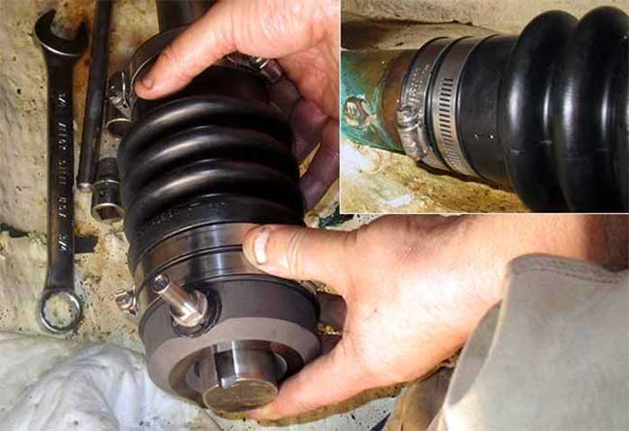
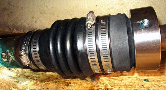
6. You can now start assembling the new shaft seal. Begin by sliding the bellows down the shaft, then clamping this to the stern tube with the two stainless-steel pipe clamps that come supplied with the shaft seal. These clamps should be oriented at 180 degrees to each other as shown. Make sure that the water-injection pipe is facing upward.
7. Slide the stainless-steel rotor collar down the shaft until it contacts the carbon ring. Do not use any sort of grease on the shaft. The two O-rings inside the collar will be damaged by grease. If some lubrication is needed to assist in sliding the collar down the shaft, use a little liquid dishwashing soap.
8. Refit the shaft coupling onto the end of the shaft, then reconnect this to the transmission. Check the transmission for shaft alignment, and adjust as necessary. Be careful not to ding the end of the shaft or coupling. Reconnect any grounding jumper cable.
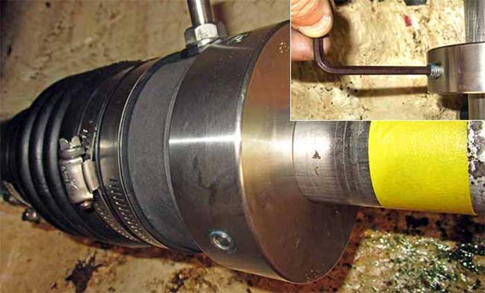
9. Compress the bellows the specified amount as outlined in the instructions. I have a 1.5-inch shaft; in my case, the amount of this compression is 1 inch. Then clamp the rotor collar to the shaft with the supplied grub screws. To set the correct compression, I used a piece of tape to mark the shaft when the bellows are "at rest," then use this as a reference to measure the correct compression. Note that there are two screws in each of the two tapped holes, one on top of the other; the first clamps the collar to the shaft, and the second acts as a lock screw. The blue stuff visible on the threads is a locking sealant.
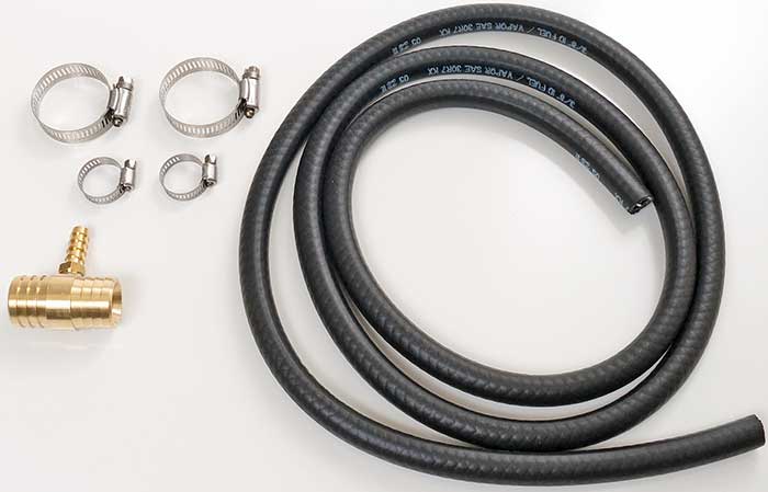
10. Connect a suitable reinforced hose from the water-injection nipple on the shaft seal to the raw-water outflow on the exhaust. (You may need to T off the pipe that injects water into the exhaust manifold.) Adequate water flow into the shaft seal's injection pipe is critical to keep the seal from overheating, which could result in its seizing. Carefully follow instructions from the manufacturer as to your specific type of boat.
As a final step, double-check your work, paying special attention to the stainless-steel hose clamps, before launching your boat.