Advertisement
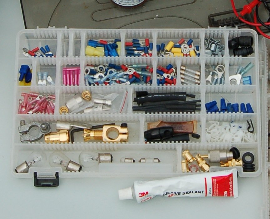
Here's The Essentials
There's nothing quite like a boat for testing an electrical circuit to its limits! At the best of times the cables and terminals must put up with a combination of the omnipresent salt atmosphere and vibration (the United States Coast Guard requires fuel tanks to be tested at up to 25 G's); at the worst of times these cables may be totally submerged in bilge water, or dripping with engine oil, or cooked at high temperatures. All too often, salt infiltrates terminals and wicks up conductors, causing corrosion and electrical resistance; vibration causes copper conductors to work harder and fracture; and oil and high temperatures degrade insulating properties, leading to short circuits. As electrical efficiency declines, equipment fails, and in worst cases fires are started.
It makes no sense to install high-quality, marine-rated electrical and electronic equipment on boats without at the same time using high quality, marine-rated cables and terminals to power the equipment. In the marine environment, "high-quality, marine-rated" is determined by the following:
- Tinned conductors, in which every strand of a cable is individually tinned to minimize corrosion.
- Multi-stranded conductors, which use what is known as Type 3 stranding to maximize flexibility and minimize the potential for work hardening and fracture.
- Heavy-duty, moisture- and oil-resistant, high-heat rated PVC insulation.
- Tin-plated, annealed copper terminals with a rugged nylon insulator designed to be double crimped so as to relieve vibration-induced stresses at the crimp.
- Heavy-wall, glue-lined, heat-shrink tubing to seal connectors against salt intrusion.
Ancor cables, terminals, and heat-shrink tubing are claimed to be built to meet these demanding standards. Properly installed, they will ensure the integrity of electrical circuits for many, many years to come.
Cable Sizing
Proper installation is primarily a matter of sizing a cable to match its tasks, using the correct tools to attach terminals, and providing adequate overcurrent protection with fuses and circuit breakers.
Cable sizing is simple enough. It is a function of the length of a cable (measuring from the power source to the appliance and back), and the current (amperage) that will flow through it. This can be found by checking the label on the appliance in the circuit, or the specifications sheet for the appliance. The longer the cable, or the higher the amperage, the bigger the cable must be to avoid unacceptable voltage losses. And there should always be plenty of extra margin for safety because an appliance may actually use more current than what it is rated for because of heat, low voltage, extra load and other factors.
For 12-volt circuits, the relationship between cable length, current flow, and cable size is given in the two tables below. Note that Table 1 presupposes a 3% voltage loss in the cable, while Table 2 presupposes a 10% voltage loss. What this means is that when the circuit is fully loaded (i.e. operating at rated amperage), the voltage at the appliance will be 3% or 10% below that at the battery. For example, if the battery is at 12.6 volts, the appliance will be seeing 12.2 volts (3% loss), or 11.34 volts (10% loss).
The cable sizing tables are used by running across the top row until the column with the relevant amperage is found, and then moving down the left-hand column until the row with the relevant distance is reached. The number in the body of the table at the intersection of this row and column is the wire size (in something known as the American Wire Gauge); the lower the number, the bigger the cable! Use this wire size (gauge) to find the correct product. But don’t hesitate to go to a heavier (fatter) wire than the table indicates.
Many appliances (notably lights) will run fine with a 10% voltage loss, but others are particularly sensitive to such losses (notably charging circuits, and some electric motors). In general, given the harsh realities of the marine environment, it's better to use the 3% volt drop table when sizing cables, rather than the 10% table. There's never a performance penalty if a cable is marginally oversized; there is always a performance penalty (and possibly a safety hazard) if it's undersized. ABYC and the United States Coast Guard require a not to exceed 3% drop for circuits involving the safety of the vessel or its passengers and in other cases.
The ground (negative) cable is as much a part of a circuit as the positive cable; it must be sized the same. In general, each appliance should be supplied from the distribution panel with its own positive and negative cables, although lighting circuits sometimes use common supply and ground cables to feed a number of lights (in which case the supply cables must be sized for the total load of all the lights).
Table 1: Wire Gauge for 3% Voltage Drop at 12 Volts |
||||||||||||||
|---|---|---|---|---|---|---|---|---|---|---|---|---|---|---|
| CURRENT (AMPS)* | ||||||||||||||
L E N G T H |
||||||||||||||
| 5 | 10 | 15 | 20 | 25 | 30 | 40 | 50 | 60 | 70 | 80 | 90 | 100 | ||
| 10' | 18 | 14 | 12 | 12 | 10 | 10 | 8 | 8 | 6 | 6 | 6 | 4 | 4 | |
| 15' | 16 | 12 | 10 | 10 | 8 | 8 | 6 | 6 | 4 | 4 | 4 | 2 | 2 | |
| 20' | 14 | 12 | 10 | 8 | 8 | 6 | 6 | 4 | 4 | 4 | 2 | 2 | 2 | |
| 25' | 14 | 10 | 8 | 8 | 6 | 6 | 4 | 4 | 2 | 2 | 2 | 1 | 1 | |
| 30' | 12 | 10 | 8 | 6 | 6 | 4 | 4 | 2 | 2 | 2 | 1 | 1/0 | 1/0 | |
| 40' | 12 | 8 | 6 | 6 | 4 | 4 | 2 | 2 | 1 | 1/0 | 1/0 | 2/0 | 2/0 | |
| 50' | 10 | 8 | 6 | 4 | 4 | 2 | 2 | 1 | 1/0 | 1/0 | 2/0 | 3/0 | 3/0 | |
| 60' | 10 | 6 | 6 | 4 | 2 | 2 | 1 | 1/0 | 2/0 | 2/0 | 3/0 | 3/0 | 4/0 | |
* Current (amps) determined by adding the total amps on a circuit.
Table 2: Wire Gauge for 10% Voltage Drop at 12 Volts |
||||||||||||||
|---|---|---|---|---|---|---|---|---|---|---|---|---|---|---|
| CURRENT (AMPS) * | ||||||||||||||
L E N G T H |
||||||||||||||
| 5 | 10 | 15 | 20 | 25 | 30 | 40 | 50 | 60 | 70 | 80 | 90 | 100 | ||
| 10' | 18 | 18 | 18 | 16 | 16 | 14 | 14 | 12 | 10 | 8 | 8 | 6 | 6 | |
| 15' | 18 | 18 | 16 | 16 | 14 | 14 | 12 | 12 | 10 | 8 | 8 | 6 | 6 | |
| 20' | 18 | 16 | 16 | 14 | 12 | 12 | 10 | 10 | 8 | 8 | 8 | 6 | 6 | |
| 25' | 18 | 16 | 14 | 12 | 12 | 10 | 10 | 8 | 8 | 8 | 6 | 6 | 6 | |
| 30' | 18 | 16 | 14 | 12 | 10 | 10 | 8 | 8 | 8 | 6 | 6 | 6 | 4 | |
| 40' | 16 | 14 | 12 | 10 | 10 | 8 | 8 | 6 | 6 | 6 | 4 | 4 | 4 | |
| 50' | 16 | 12 | 10 | 10 | 8 | 8 | 6 | 6 | 4 | 4 | 4 | 4 | 2 | |
| 60' | 16 | 12 | 10 | 8 | 8 | 8 | 6 | 4 | 4 | 4 | 2 | 2 | 2 | |
* Current (amps) determined by adding the total amps on a circuit.
Terminals and Tools
Terminals need to be matched to their cables. A 16-gauge cable needs a 16-gauge terminal. However, the same-sized terminals are sometimes used for more than one cable size. Red terminals fit 22 to 18 gauge cables, blue terminals 16 to 14 gauge cables, and yellow terminals 12 to 10 gauge cables. In larger sizes, each cable has matching terminals.
The terminals are the weak link in an electrical circuit. If installed incorrectly, they're likely to create power-robbing resistance. Since resistance causes heat, fires can result from improperly installed terminals. Crimp-on terminals have gained universal acceptance in marine wiring, but to work effectively they must be put on with the proper tools. For marine electrical work you need a wire stripper (rather than a pocket knife, which is likely to nick the copper strands in the conductor), and a decent crimping tool. The crimper needs to be matched to the terminal size being crimped, and should preferably make a double crimp, once on the conductor and once to grip the insulation for strain and fatigue relief.
For the ultimate in terminal protection and longevity following crimping, a connection can be protected with a length of glue-lined, heat-shrink tubing. Properly applied, this will make the connection watertight; the connection should last the life of the boat.
Overcurrent Protection
Overcurrent protection is a frequently misunderstood subject. Its need arises from the fact that if a short circuit develops in onboard wiring, high current flows occur, generating heat and causing cables to melt down. If the short is a serious one (a "dead short"), cables can burst into flames, setting fire to the boat and its surroundings. Electrical fires are among the most common fires onboard.
Fuses and circuit breakers, which collectively are known as overcurrent protection devices, are the primary defense against electrical fires. To be effective, they must meet two conditions: they must be properly sized for their circuit, and they must be placed as close as possible to the electrical source for the circuit.
Sizing is a function of the cable sizes in the circuit, not the amperage draw of the appliance in the circuit. A fuse or circuit breaker is sized to protect the smallest wire in its circuit. The current-carrying capability (ampacity) of this wire is determined by referring to Table 3, and then a fuse or circuit breaker is chosen with a rating no higher than this (it can be lower). If there is not an exact match between cable ampacity and available fuse or circuit breaker ratings, an overcurrent device with a rating of up to 150% of the ampacity of the cable can be used, but that's the limit.
There are two columns in the ampacity table-one for use outside engine spaces, and one for use inside engine spaces. The reason for this is that engine rooms are usually hot. Even before a circuit is turned on, a cable is warm. In these conditions it takes less current flow to bring the cable to a dangerous temperature than it does in a colder environment; hence, the de- rating in high ambient temperatures. If any part of a circuit runs through engine room spaces, the lower ampacity rating is used to determine the proper overcurrent protection for that circuit.
To be effective, overcurrent protection devices must be installed as close as possible to the source of power for a circuit. In fact, the ABYC recommends that circuits be fused within 7" of their connection to a power source. There are some exceptions to this recommendation, notably cranking circuits (these require no protection at all), circuits that are connected directly to a battery post (in which case the 7" is extended to 72"), and cables which are housed in a sheath (in which case the 7" is extended to 40"), but in general the point needs to be made: every circuit should be provided with a properly sized overcurrent protection device at the circuit's connection to a power source. If you've got a bunch of cables hot-wired to your batteries with no overcurrent protection, not only are these circuits not recommended, but you're also inviting a fire!
Circuit breakers and fuses are available for anything from a fraction of an amp up to 800 amps. There are also available a wide array of fuse blocks and distribution panels for mounting these fuses and circuit breakers. The complexity of wiring considerations can be seen in the following and above tables, all of which indicate that wiring should be done by an ABYC certified specialist unless you really know what you are doing and can follow ABYC standards.
Table 3: Ampacity |
||
|---|---|---|
| AWG | Engine Space Outside | Ampacity Inside |
| 18 | 20 | 17 |
| 16 | 25 | 21 |
| 14 | 35 | 30 |
| 12 | 45 | 38 |
| 10 | 60 | 51 |
| 8 | 80 | 68 |
| 6 | 120 | 102 |
| 4 | 160 | 136 |
| 2 | 210 | 178 |
| 1 | 245 | 208 |
| 1/0 | 285 | 242 |
| 2/0 | 330 | 280 |
| 3/0 | 385 | 327 |
| 4/0 | 445 | 378 |
Table 4: Marine Wire Color Code |
||
|---|---|---|
| Color | Item | Application |
| Yellow or Black | Ground | Return, Negative Mains |
| Light Blue | Oil Pressure | Oil Pressure Sender to Gauge |
| Dark Blue | Cabin & Instrument | Fuse or Switch to Lights |
| Brown | Generator Armature | Generator Armature to Regulator |
| Brown | Alternator Charge Light | Generator Terminal or Alternator Auxiliary Terminal to Regulator |
| Brown | Pumps | Fuse or Switch to Pumps |
| Green | Bonding System | Bonding Wires (if insulated) |
| Gray | Navigation Lights | Fuse or Switch to Lights |
| Gray | Tachometer | Tachometer Sender to Gauge |
| Orange | Accessory Feed | Ammeter to ALternator, Generator Output and Accessory Fuses or Switches |
| Orange | Common Feed | Distribution Panel to Accessory Switch |
| Pink | Fuel Gauge | Fuel Gauge Sender to Gauge |
| Purple | Ignition | Ignition Switch to Coil & Electrical Instrument |
| Purple | Instrument Feed | Distribution Panel Electrical Instruments |
| Red | Main Power Feeds | Positive Mains (particularly unfused) |
| Yellow | Generator Field | Generator to Regulato Field Terminal |
| Brown w/Yellow | Bilge Blowers | Fuse or Switch to Blower |
| Yellow w/Red | Starting Circuit | Starting Switch to Solenoid |
Miscellaneous
Other important points to bear in mind when wiring boats:
- All circuits should be as high as possible with no connections in or near bilge water or damp areas.
- Use twisted-pair conductors for any wiring within three feet of a compass.
- You should never tap into existing circuits when installing new equipment; run a properly-sized new duplex cable (positive and negative conductors in a common sheath) from the distribution panel (or a source of power) to the appliance.
- All conductors should be labeled at both ends, and you should keep an updated wiring plan on board, to aid in future troubleshooting.
- Each circuit should have an independent ground cable, and all the ground cables should eventually be tied back to a common ground point which is grounded to the battery negative; if devastating stray current is to be avoided, this is the only point at which the grounds should be interconnected.
- Unless in a conduit, cables should be supported at least every 18".
- Although black is often used for DC negative, it is also used for the live wire in AC circuits. That means there is potential for dangerous confusion. Instead, you should use yellow for DC negative wherever possible.
- High-quality coax cable is critical to the effective functioning of radios; use only fully-tinned, 96% braid coax, and ensure that all connectors and terminals are properly installed.
- DC and AC wiring should be kept separate; if they have to be run in the same bundle, one or the other should be in a sheath to maintain separation and ensure safety.
- Be sure to isolate the batteries before working on the DC system, and, for safety's sake, shut off all potential AC power sources (the shorepower cord, an onboard AC generator, or an inverter).